Base Station
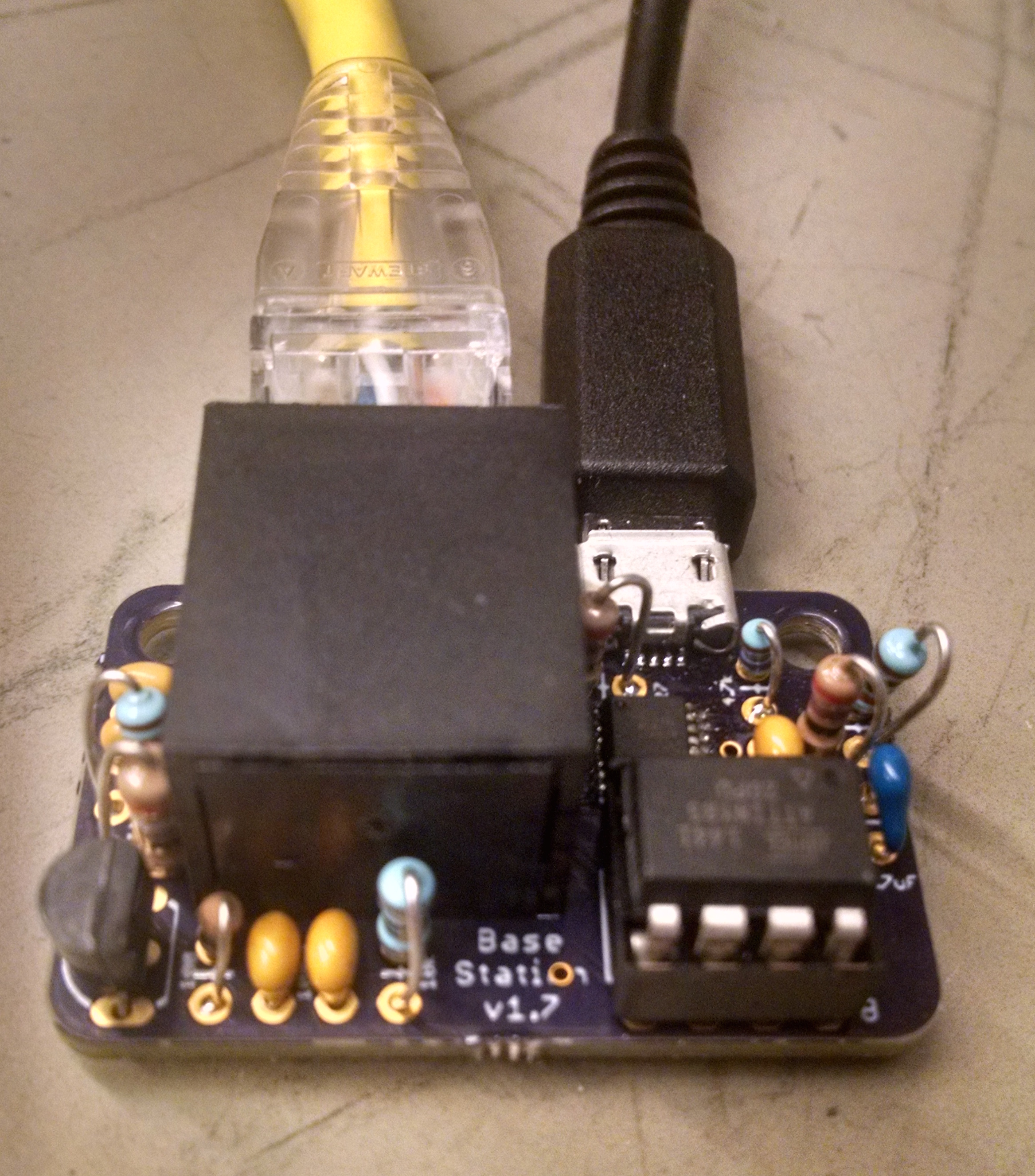
Specifications
| Parameter | Test Condition | Value | Unit |
|---|---|---|---|
| Supply Voltage | 5 | V | |
| Current | 97 | mA | |
| Transmission distance | 5 | m |
Bill of Materials
| Qty | Description | Datasheet | Vendor |
|---|---|---|---|
| 1 | Base Station PCB | OSH Park | |
| 1 | Microcontroller | ATTINY85 |
Octopart |
| 1 | FTDI USB to Serial Converter | FT230X |
|
| 1 | Infrared LED | VSMS3700 |
|
| 1 | RJ45 Horizontal connector | 54602-908LF |
|
| 1 | Female micro USB horizontal socket | 10118193-0001LF |
|
| 1 | NPN Transistor | PN2222A |
|
| 2 | 0805 27 Ω Resistor | ||
| 1 | 1/4W 39 Ω Resistor | ||
| 1 | 0805 4.7 kΩ Resistor | ||
| 3 | 0805 10 kΩ Resistor | ||
| 1 | 0805 100 Ω Resistor | ||
| 2 | 0805 4.7 μF Capacitor | ||
| 2 | 0805 100 nF Capacitor |
Design Files
Build Instructions
Required Tools
- Soldering iron
- Tweezers
FTDI USB to Serial Converter Setup
The FTDI USB to serial converter should be setup such that it is powered from the Base Station PCB, not powered over USB. In order to implement this, the settings on the chip’s EEPROM need to be modified. FTDI provides a utility to do this, which you should download here
- Open up Device Manager and reveal the Ports (COM & LPT) list
- Connect the Base Station to the computer over USB. It should Appear under ports as “USB Serial Port (COMxx)”
Error
If the device doesn’t appear int he Ports list at all, you many need to connect power to the Base Station via the RJ45 jack or DC input jack
Error
If the device appears in the Ports list as an “Unknown device”, then you can manually download and install the FTDI FT230X Driver
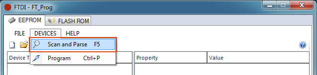
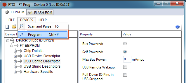
- Open up FT Prog and go to DEVICES–>Scan and Parse
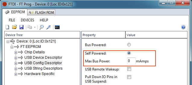
- Select “USB Config Descriptor” in the Device Tree. Select “Self Powered” and change the “Max Bus Power” to 0.
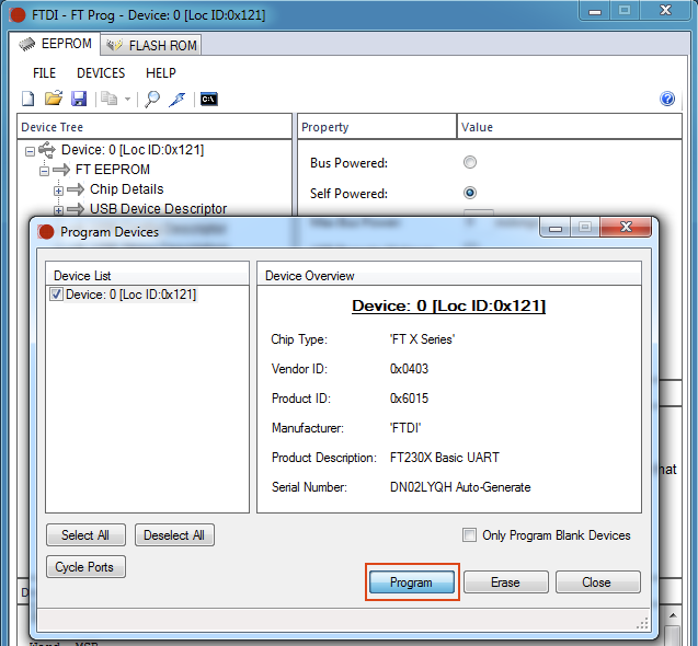
- Go to DEVICES–>Program
- Click “Program”
Uploading Firmware
Attention
If you have not yet setup the Arduino environment or the Cerebro Utility Shield, refer to Setting up Arduino IDE and/or Setting up Utility Shield before moving on.
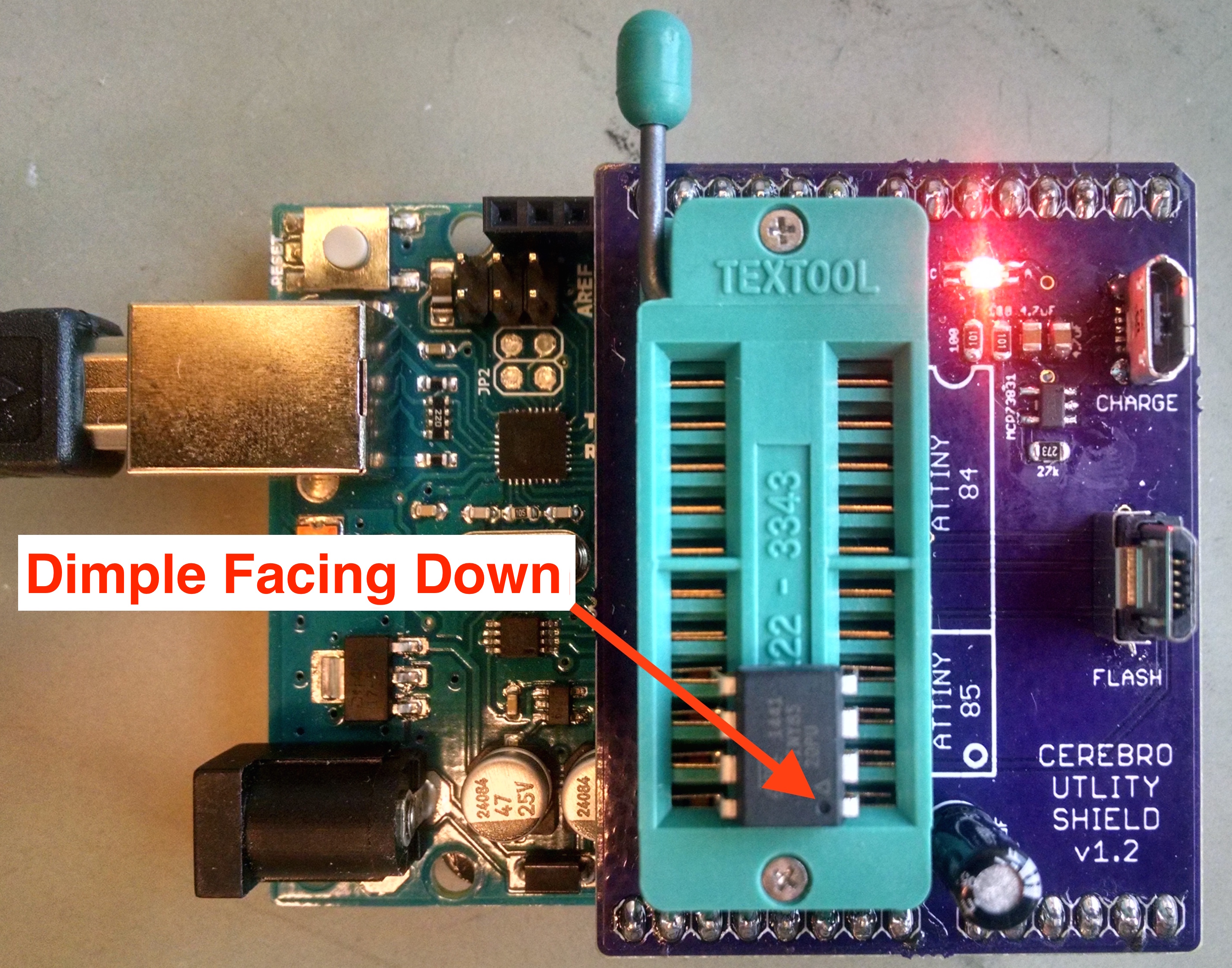
- With the notch facing down, place the chip in the lower portion of the Utility Shield’s ZIF socket.
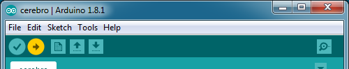
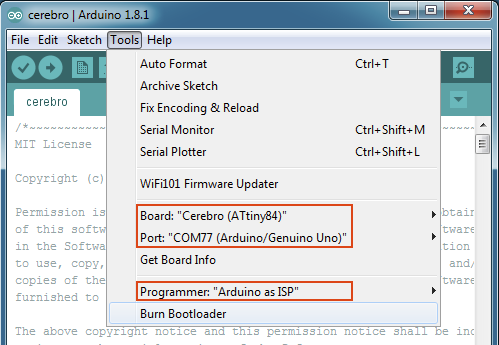
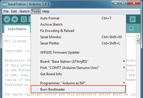
- Open up the Arduino application and make the following selections under the Tools menu:
Board: “Base Station (ATtiny85)”
Port: “COMXX (Arduino/Genuino Uno)”
Programmer: “Arduino as ISP”
- Burn the bootloader by selecting Tools -> Burn Bootloader
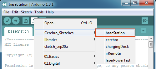
- Choose the Base Station firmware by going to File -> Sketchbook -> Cerebro Sketches -> baseStation
- Upload the firmware by clicking the upload arrow